Instructions for the Use of the Starlink Portable Power Device
The Starlink Mini antenna is designed to utilize an average of 22 watts of power while it is operating normally. The antenna is produced by Starlink and is about the size of a sheet of paper. It includes an integrated wifi router for client connections.
Both the survival case and backpack are designed specifically to power the Starlink Mini system. A retrofit can be added for Gen 3 antenna’s for the survival case, but it will consume more power and decrease battery life (80-100 watts draw)

The Starlink Power Backpack Description
The Backpack is designed with a 32 amp hour cold weather lithium battery, which is designed to last up to 18 hours of continuous usage of an average of 22 watts of power draw (does not include power draw from phones, ipad’s, or heating the Starlink antenna).
- Battery service and charging temperature is -4 degrees Fahrenheit
The backpack is built into a waterproof case and can be removed from the backpack
- All of the attachment cables are can be pulled out for connections
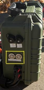
- Two power switches, one for the charging system and one for the satellite system.
- There are two high speed USB-C ports for phone or ipad charging.
On the inside of the case are the following components
- One 120 watt foldable solar panels
- Connection cords
- 120vac shore power connection
- 12vdc car charger (Alternator must be on) connection.
- Solar power connection
- All connections are made with colored MC-4 connectors. They can typically be disconnected by hand or with the included tool.
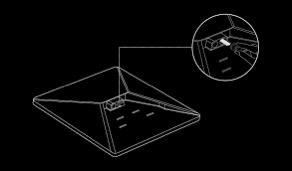
- For Starlink and the solar panels to operate correctly, they must have a clear viewe of the sky
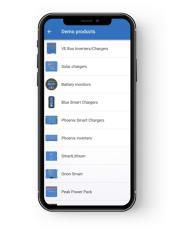
- Starlink activation and mobile application are required for operation
- The Victron application is not required, but recommended to see the state of the battery and solar modules
Colored Connector Chart (MC-4 Connectors). The splitters are either male or female for each color. As long as the color is matched, the connections cannot be setup incorrectly. Each cable is also labeled with letters, so they can be matched if the colors cannot be seen
| Orange (two connections) B | Solar panels patch cable PEM Side |
| Grey (two connections) BB | Solar panels patch cable splitter side |
| Green (four connections) BBB | Solar panels patch cable to splitter end |
| White (four connections) BBBB | Solar panels patch cable to solar panels |
| Blue (two connections) C | 120vac shore power |
| Yellow (two connections) D | 12vdc car power |
Backpack Installation Steps
Which Power do you want to use?
Internal battery only
- Pull all of the cables out of the backpack. They will all have colored MC-4 connectors
- Connect the Black Starlink MC-4 connector patch cable to the black MC-4 cable from the backpack
- Connect the far end barrel connector to the port underside the starlink antenna
- Activate the charging system button
- Connect to the Starlink SSID (default), or custom SSID if enabled
- Open the Starlink app on your mobile device and check that is online
- Open the Victron power App and go to the “SmartShunt”. The battery state as well as power draw and time remaining are shown
- The SmartShunt power draw will show a negative amperage of approx.. 22 watts
- End of battery setup
Solar Power
- Use all the steps for battery only to activate the system
- Take the solar panels, patch cables, and lay them out by color
- Make all connections (The unit can remain on during this setup step)
- Attach to the orange patch cable to the orange backpack MC-4 connectors
- Setup the solar panel and angle it to point at the sun
- Check the Victron power app to ensure the solar module is showing a charge. The Smartshunt module will also show a positive amperage flow
- Sun tracking- The most efficient way to harvest sun power
- Ideally
- End of solar setup
120 VAC
- Use same steps for the battery to setup system. Solar setup is not required
- Connect the blue wall plug to the blue MC-4 connectors from the backpack
- An additional AC power module will be added to the Victron app. It should now show ~15 amps of charge. The “Smartshunt” will als show a positive amperage (note, with the Starlink system running, it will consume ~1.5 amps of power. The total charge amperage to the battery will be ~13.5 amps
- End of AC setup
12vdc (Car alternator charging)
- Use the same steps as the battery to setup the system
- Connect the yellow alligator clamps to the yellow MC-4 connectors from the backpack
- Attach the alligator clamps to the car battery
- The DC module will NOT charge the system without the car enginee on and the alternator charging to 14 volts (idle is usually ok)
- Check the Victron app “Smartshunt” to see a positive amperage. The DC module is rated for 8 amps max. 6.5 amps to the battery with the Starlink system running